Weld preparation is a of the most labor-hungry steps in heavy fabrication. Parts are cut square, then moved to a grinder, a beveling machine, or a milling station so the edges can take a full penetration weld. Every move adds handling time and a chance for error. Laser bevel cutting folds that step into the cut itself, which is why structural steel, pressure vessel, and heavy equipment fabricators are adopting it.
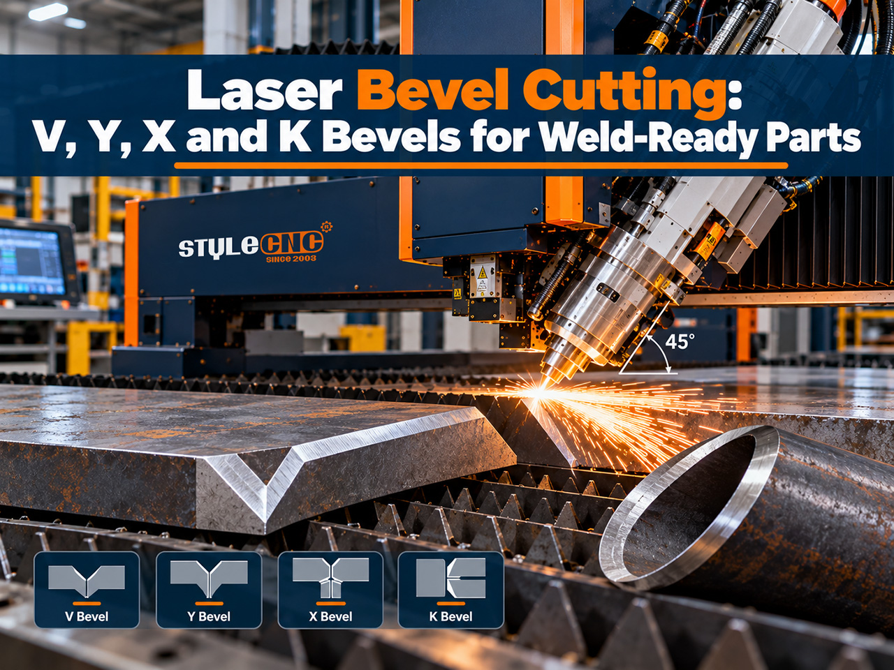
Bevel Types: V, Y, X and K
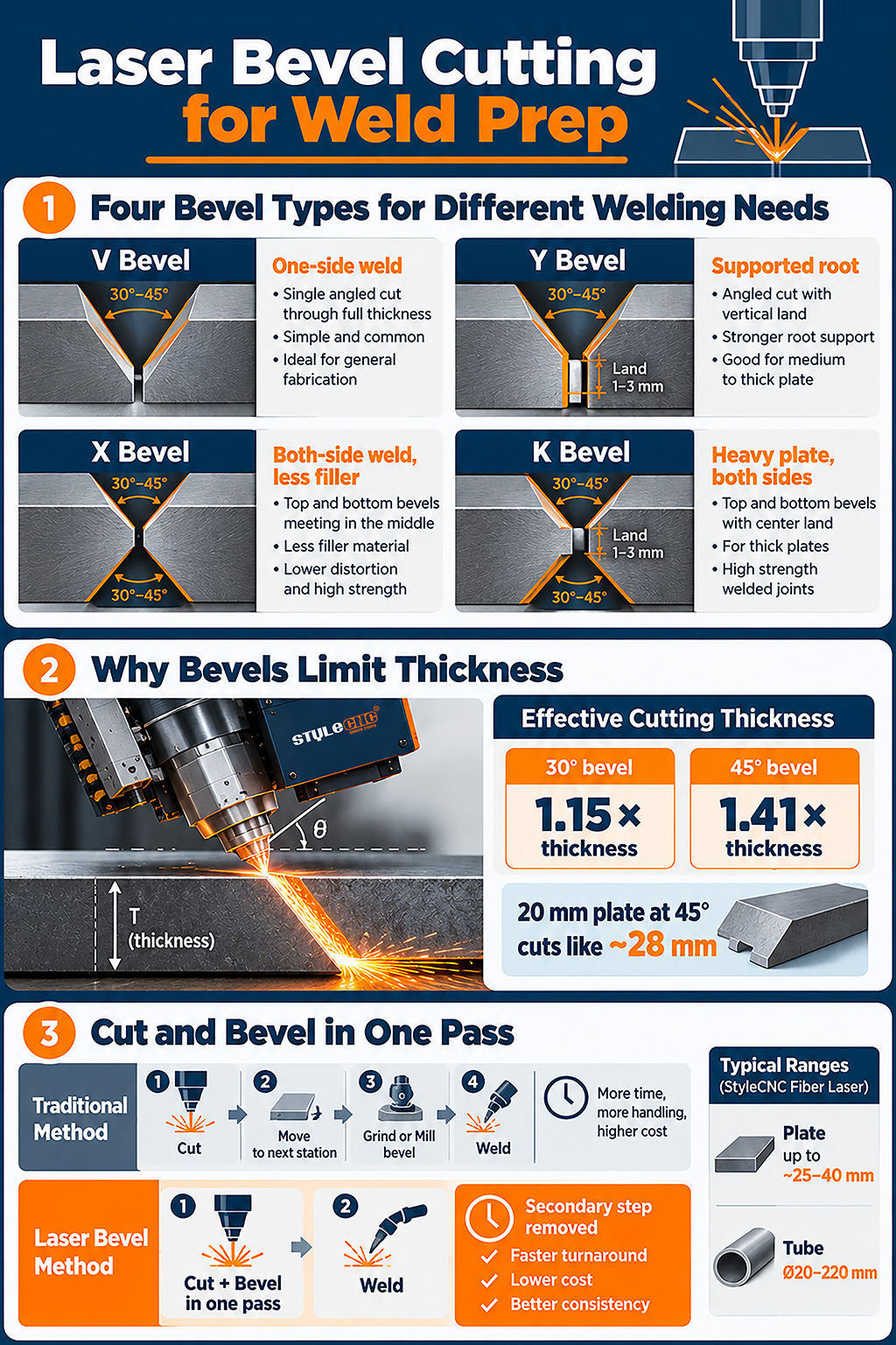
The 4 common bevel shapes are named for the profile they leave on the edge. The right 一つ depends on plate thickness, whether the joint can be welded from 一つ side or both, and what the weld procedure calls for.
| 斜角タイプ | ジオメトリ | 典型的な使用 | Welding Side | サイズ測定 |
|---|---|---|---|---|
| V (or A) | One angled cut through the full thickness; A is the same cut from the underside | Thin to medium plate welded from 一つ side | 片側 | Bevel angle, checked with a protractor gauge |
| Y | Angled cut with a straight vertical land (root face) at the bottom | Full penetration welds where the root needs support | 片側 | Land h8 and bevel angle |
| X | 2 angled cuts, top and bottom, meeting in the middle | Thicker plate welded from both sides to reduce distortion and filler | 両側 | Top and bottom angles and their meeting point |
| K | Top and bottom bevels with a vertical land between them | Heavy plate needing both-side welds with a defined root | 両側 | Both angles plus land height |
A few practical rules guide the choice:
⦿ Single-sided V and Y bevels suit joints that can only be reached from 一つ side, or thinner plate where 一つ pass fills the groove.
⦿ Double-sided X and K bevels use less filler metal on thick plate and balance distortion, because heat goes in from both faces.
⦿ A land, as on Y and K bevels, gives the root pass something to fuse against and reduces burn-through.
⦿ Bevel angles for weld preparation commonly fall between 20 and 45 degrees, with 30 to 37.5 degrees a frequent choice.
The groove geometry for code work is set by the weld procedure specification, not by the cutting machine. Always program bevels to match the procedure your welders are qualified to, and confirm whether the applicable code requires thermally cut surfaces to be cleaned before welding.
認定条件 3D Bevel Heads Work
A standard laser head cuts straight down. A bevel head adds 2 rotary axes that tilt and rotate the nozzle, so the beam can enter the material at an angle while the machine follows the part contour. Combined with the usual X, Y, and Z motion, that gives 5 axes of movement, which is why these systems are often described as 3D or 五軸 laser bevel cutting.
The control software coordinates all 5 axes so the nozzle keeps the right angle and standoff distance around corners and curves. Good systems also calibrate the tool center point automatically, because a small error in the head geometry turns into a visible error in the bevel angle and land. Bevel heads on current machines typically cover ±45 degrees, and some extend slightly beyond that.
Why thickness limits are lower when beveling
An angled cut passes through more metal than a straight one. The effective cut length equals the plate thickness divided by the cosine of the bevel angle:
⦿ At 30 degrees, the beam cuts through about 1.15 times the plate thickness.
⦿ At 45 degrees, it cuts through about 1.41 times the plate thickness, so 20 mm plate behaves like roughly 28 mm.
That is why 一つ published bevel head rates direct beveling up to about 35 to 40 mm depending on the angle, but only about 28 mm for a full 45 degree bevel. Higher laser power extends these limits, and shops beveling thick plate regularly tend to choose heavy-duty fiber laser cutting machines with the frame stiffness to hold bevel accuracy across large plates.
Programming and nesting beveled parts
Bevel parts need a little more planning than straight-cut parts. Because the beam leaves the top surface at an angle, the cut on the underside sits offset from the top contour, so parts need more spacing in the nest and common-line cutting is usually off the table. Lead-ins and corner handling also change, since the head must re-orient at sharp corners without gouging the bevel.
Most bevel-capable controls let the programmer assign a bevel type, angle, and land to each edge of a part, and keep straight edges on the same part vertical. That mixed approach is what lets a single base plate come off the table with square sides, beveled weld edges, and bolt holes in 一つ program.
Laser vs Plasma vs Milling for Bevels
Laser is not the only way to bevel. Plasma bevel heads have been used on thick plate for years, and milling or dedicated edge-beveling machines remain the reference for precision. Each has its place:
| 因子 | Laser Bevel | Plasma Bevel | フライス加工 | サイズ測定 |
|---|---|---|---|---|
| Bevel accuracy | High; small kerf and tight angle control | Good, with a wider kerf and more angle variation | Highest, machined surface | Angle and land deviation across a batch |
| 熱影響部 | S | より大きい | なし | HAZ width on a sectioned sample |
| 厚さ範囲 | Best up to about 25 to 40 mm, less at 45 degrees | Extends into heavier plate | Any thickness, slowly | Maximum thickness at your bevel angle |
| プロセスステップ | Cut and bevel in 一つ operation | Cut and bevel in 一つ operation | Separate operation after cutting | Handling steps per part |
| 資本コスト | 最高 | 低くなる | Moderate per machine | Installed cost against labor saved |
Fabricators often put the trade-off simply: if every bevel still has to go to the grinder before the welder accepts it, the bevel head has not paid for itself. Laser bevels tend to win where angle and land consistency matter, because tight fit-up reduces filler metal and repair welds. Testing on 12 mm structural steel has shown laser-cut bevels producing a smaller heat-affected zone than other thermal processes, which helped the finished weld.
Plasma remains the practical option for very thick plate and rougher structural work, as covered in the overview of laser cutting vs plasma cutting machines. Milling still makes sense for the tightest tolerances or for parts that must be machined anyway. For most medium plate weld preparation, a laser bevel head now covers the job in 一つ pass.
Cut quality on bevels needs a slightly different eye than on straight cuts. Dross tends to collect on the lower, acute side of an angled cut, and the land on Y and K bevels must stay square and to size for the root pass to work. Nozzle choice, gas pressure, and cutting speed are tuned per angle, and good machines store those settings in a bevel process library so operators are not starting from scratch on every job.
Sheet and Plate vs Tube Beveling
Plate beveling
On flat plate, the bevel head follows the part outline across the bed. Typical working ranges quoted for plate beveling run from about 8 to 40 mm on mild steel, 6 to 25 mm on stainless, and 6 to 20 mm on aluminum, depending on laser power and bevel angle. Parts such as flanges, gussets, base plates, and pressure vessel shell sections come off the table with weld edges already formed. Shops cutting this kind of structural and plate steel see the clearest labor savings.
Tube and pipe beveling
Tube beveling adds rotation to the equation. The tube turns in chucks while the head tilts, so the machine can cut end bevels, saddle joints, and fish-mouth profiles where 一つ tube meets another. Typical tube bevel ranges cover diameters from around 20 to 220 mm with wall thickness up to roughly 8 mm, and larger on bigger machines. A 3D チューブレーザーベベル切断機 handles these joints in 一つ setup, which replaces the manual marking, sawing, and grinding usually needed for pipe and frame fit-up.
Tube work also needs good support. Multi-chuck designs and follower supports keep long tubes from sagging or whipping while they rotate, which matters more when the head is tilted. Shops that cut tube without bevels today often start with a ファイバーレーザーチューブ切断機 and move to a bevel model once weld prep becomes the bottleneck. Formed or 3-dimensional parts that need trimming as well as beveling are a job for 3D robotic fiber laser cutting machines.
Where Bevel Cutting Pays Off
⦿ Structural steel: base plates, gussets, and connection plates with weld preparations cut in 一つ pass.
⦿ Pressure vessels and tanks: shell and nozzle preparations where consistent groove geometry supports qualified procedures.
⦿ Heavy equipment: frames and booms with many thick-plate welds and repeat part numbers.
⦿ Pipe and frame fabrication: tube end bevels and saddle joints that otherwise need manual layout and grinding.
The common thread is volume of welded joints. The more bevels a shop grinds by hand each week, the faster a bevel head pays back. Consistent bevels also make the next step easier, whether parts go to manual welders, robots, or レーザー溶接機 that depend on tight fit-up.
A simple labor estimate
Consider an illustrative shop that grinds weld preparations on 200 parts a week at about ten minutes per part. That is more than 30 hours of grinding every week, before rework on bevels that come out uneven. If a bevel head moves most of those parts to the cutting table, the saved hours are close to a full-time position, and the remaining bevels arrive more consistent for the welders. Replace the part count and minutes with your own figures to see where the payback lands.
Bevel Cutting Checklist
✔ List the bevel types, angles, and land heights your weld procedures specify.
✔ Check your thickest beveled parts against the machine’s rated thickness at your steepest angle.
✔ Measure how many hours a week go into grinding or milling weld preparations today.
✔ Confirm automatic head calibration and bevel programming in the control software.
✔ Cut test coupons and have them checked against your procedure before moving production.
Cut Weld-Ready Bevels in 一つ Pass
See the specifications, bevel range, and tube capacity of the 3D チューブレーザーベベル切断機, and get a free quote based on your tube sizes, plate thicknesses, and weld preparation requirements.